← Back to FlowFraming
Revit Plugin Documentation

FlowFraming User Manual

Automated wood framing for Revit
v2.10.3 Revit 2021–2025
01 — Introduction

Introduction

FlowFraming is a Revit plugin that automatically generates code-compliant wood stud framing for walls and floor joist framing for slabs and floors. It is designed for residential and light-commercial architects, structural drafters, and BIM coordinators who need accurate framing assemblies directly inside Revit — with scheduling, cut lists, Excel exports, and dimensioned shop-drawing views — without leaving the modeling environment. The plugin adds a dedicated Wood Framing ribbon tab containing three panels: Wall Framing, Floor Framing, and Tools — the last holding the BOM export, type presets, and the assembly-view, annotation and clean-up commands.

02 — Before You Start

Before You Start

Load a wood structural framing family into your project once per project: Insert > Load Autodesk Family > Structural Framing > Wood > Dimension Lumber. Any structural framing family works, but dimension-lumber families give true 2x sizes because they expose width and depth (b / h) type parameters.

To get meaningful assembly names, fill in each wall's Mark parameter — for example Wall A-01 — before framing.

Open a floor plan view before running the framing commands. Dimensions and tags land correctly there.

Tip: Selecting walls before launching a command uses that selection directly, skipping the pick step.
03 — Getting Started

Getting Started

System Requirements

  • Autodesk® Revit® 2021–2025
  • Windows 10 or Windows 11 (64-bit)
  • Microsoft Excel (optional, required to open exported BOM files)

Installation

  1. 1Close Revit if it is currently open.
  2. 2Copy WoodFraming.addin and WoodFraming.dll to %AppData%\Autodesk\Revit\Addins\<your Revit version>\ — paste this path into File Explorer's address bar to navigate there directly.
  3. 3Launch Revit and open any project.
  4. 4Confirm that the Wood Framing tab appears in the ribbon.

The full Revit ribbon showing the
04 — Concepts

Concepts

Assemblies

Every time a wall or floor is framed, all generated members are grouped into a Revit Assembly linked to that element. Assemblies make it easy to schedule, tag, and manage framing as a unit — selecting the host element gives you access to its entire framing assembly.

Presets

A preset is a named snapshot of framing settings (spacing, member sizes, rim counts, etc.) saved per project. Presets can be mapped to specific Revit wall or floor types so the correct configuration loads automatically whenever you frame an element of that type, with no manual selection required.

Auto-Update

When Auto-Update is enabled for a framed element, the plugin monitors that element for geometry and opening changes and re-frames it automatically. When Auto-Update is off, use the Update Framing or Update Floor Framing button to refresh framing after a change.

BOM / Cut List

The plugin writes member size, role, and length data into each element's Comments parameter as framing is generated. This data can be exported at any time to an Excel workbook containing a detailed cut list and a rolled-up summary — no re-framing required.

Assembly Naming

Assemblies take their name from the host wall’s Mark parameter — a wall marked "Wall A-01" produces "Wall A-01 Framing". A wall with no Mark falls back to "{Wall type name} Framing 01", numbered sequentially, and duplicate names get a "(2)", "(3)" suffix automatically. Fill in the Mark before framing to get meaningful names.

Assembly Views

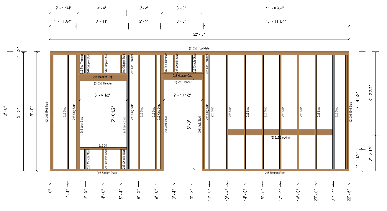
Because every framed element is grouped into a Revit Assembly, the plugin can generate a full set of shop-drawing views directly from it — interior and exterior elevations, end elevations, a plan detail, two detail sections, a 3D view, a part list and a material takeoff — for walls and floors alike. Views are driven by reusable presets and land in the project browser; an assembly sheet is optional, so sheet layout stays under your control.

Dimension Groups

Every member the plugin places records its size and role in its Comments parameter, for example “2x4 King Stud”. That is what groups the framing for annotation: each member type gets its own dimension chain with its own style, anchor, side and offset, so a stud layout string, a plate height and an opening width never share a line. It is also what the labels and the BOM read, so leave the Comments alone.

Recorded Annotation

Each annotation pass records exactly which dimensions and text notes it created on the view itself. Delete Dimensions and Delete Labels use that record to remove the plugin’s own work and leave anything you drew by hand untouched — and each leaves the other kind alone, so you can re-dimension without losing your tags.

05 — Wall Framing

Wall Framing Panel

1. Frame Wall
Generates stud framing for one or more selected walls.
  1. Select one or more walls in the model.
  2. Click Frame Wall.
  3. If a Type Preset is mapped to the wall's Revit type, framing generates immediately using that preset — no dialog appears.
  4. Otherwise, the Wall Settings dialog opens; configure options and click OK.
  5. If framing already exists on a selected wall, the plugin asks you to confirm replacement before proceeding.
  6. Click Preview & Frame — a summary reports how many studs, plates and headers will be placed and how many openings will be framed. Nothing is modified until you choose Yes.
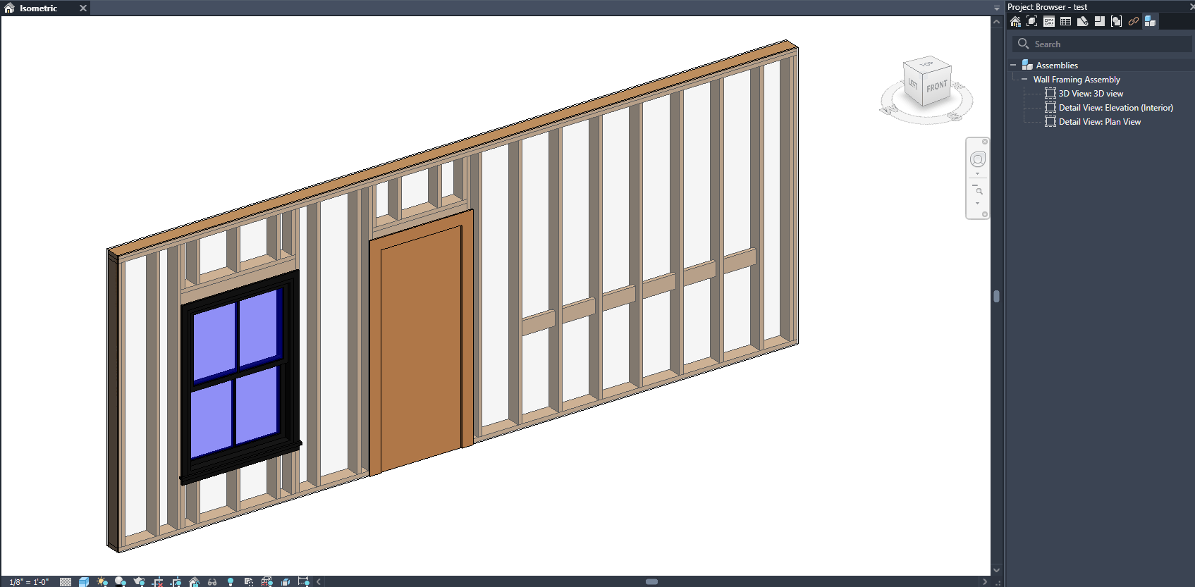
A framed wall in the Revit 3D view showing studs, plates, headers above an opening, and the Revit Assembly visible in the Properties panel
2. Framing Configuration (Wall)
Opens the Wall Settings dialog to review, edit, or save presets — with or without a wall selected.
  1. Optionally select walls in the model.
  2. Click Framing Configuration in the Wall Framing panel.
  3. Adjust settings as needed.
  4. Click Save to store the configuration as a named preset, or click OK to apply and close.
  5. If walls were selected, the new settings are applied to those walls immediately.
Tip: Use this button to manage presets without re-framing — select a saved preset from the dropdown to load it, then save under a new name if needed.
3. Add Blocking
Adds one or more rows of horizontal blocking to already-framed walls.
  1. Select one or more framed walls.
  2. Click Add Blocking.
  3. In the dialog, set the number of blocking rows and the spacing height.
  4. Click OK — blocking is inserted between studs at the specified heights.
  5. Blocking re-snaps to the nearest member automatically when the layout later changes.
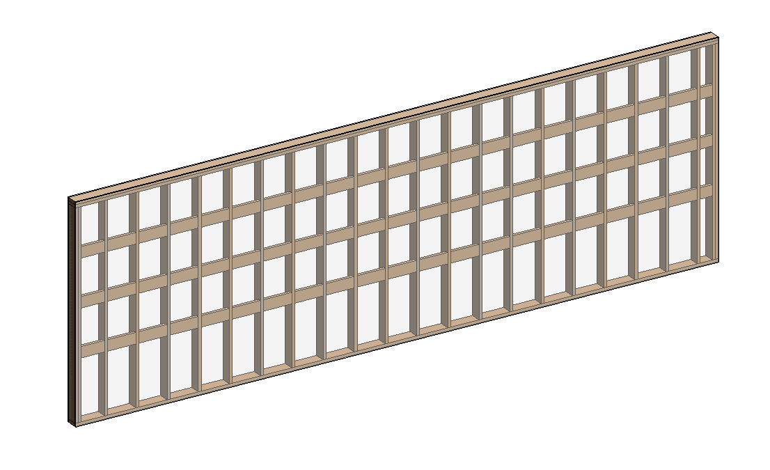
A framed wall with horizontal blocking rows visible between studs in a Revit 3D or elevation view
4. Delete Blocking
Removes only the blocking from selected framed walls, leaving studs, plates and openings untouched.
  1. Select one or more framed walls that have blocking.
  2. Click Delete Blocking.
  3. Confirm the deletion — only blocking members are removed.
Tip: Use this to re-run Add Blocking with different rows or heights without re-framing the whole wall.
5. Delete Framing
Removes all framing members, the assembly, and the stored framing state from selected walls.
  1. Select one or more framed walls.
  2. Click Delete Framing.
  3. Confirm the deletion in the prompt.
Warning: This action is irreversible. All framing members are permanently deleted from the model.
6. Update Framing
Re-runs framing on selected walls using their saved configuration.
  1. Modify wall geometry or openings in Revit as needed.
  2. Select the affected framed walls.
  3. Click Update Framing — the plugin re-frames using the previously saved settings.
Note: If Auto-Update is enabled for a wall, updates happen automatically and this button is only needed as a manual override.
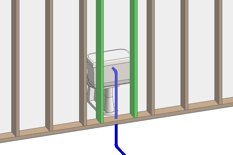
7. Shift Studs
Moves individual stud stations to avoid conflicts with plumbing, ducts, or other obstacles.
  1. Select a framed wall.
  2. Click Shift Studs.
  3. Click one or more studs in the model to identify which stations to move.
  4. In the dialog, set the offset distance and choose a mode: Keep Original — the original stud stays and a shifted copy is added. Eliminate — the original stud is removed and replaced at the new position. Eliminate + Add Special — removes the original and places a shifted stud plus an additional "special" stud at a separately configured distance.
  5. Click OK to apply. Shifted members receive a Special comment in their Comments parameter.
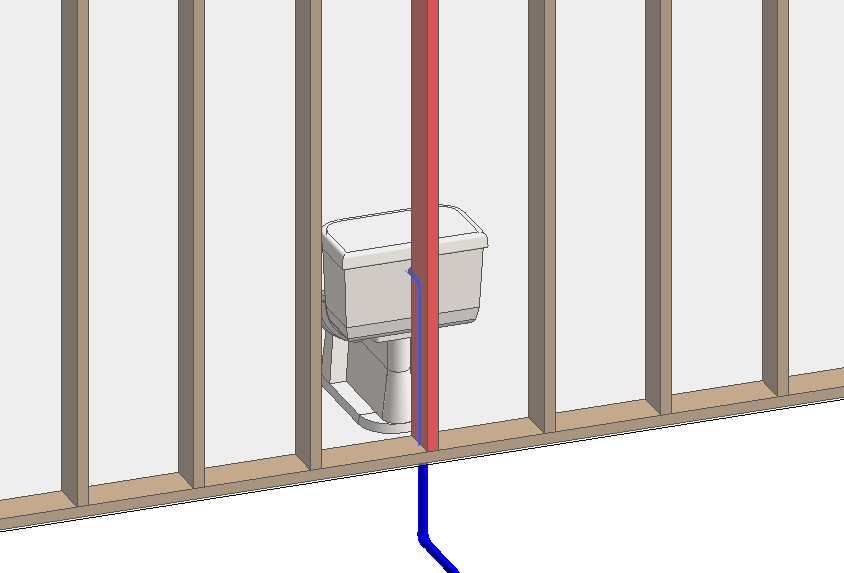
A wall elevation or 3D view showing a shifted stud with a visible gap at the original station and the new stud position highlighted A wall elevation or 3D view showing a shifted stud with a visible gap at the original station and the new stud position highlighted
8. Flip O.C. Layout
Cycles the layout origin between Start, End, and Centered to shift the entire stud pattern along the wall.
  1. Select one or more framed walls.
  2. Click Flip O.C. Layout.
  3. The button label updates to display the new mode. Framing is regenerated immediately using the new origin.
Note: The selected mode is saved with the wall's framing state and persists through future Update Framing operations.

Wall Settings Dialog

The following fields are available in the Wall Framing Configuration dialog:

The Wall Framing Configuration dialog: spacing, stud size, plates, placement, layout origin, corner and T styles, with the schematic preview
Field Description
O.C. Spacing On-center stud spacing (e.g., 16", 19.2", 24").
Stud Size Lumber size for vertical studs (e.g., 2×4, 2×6).
Start Offset Distance (inches) to trim framing away from the wall's start end.
End Offset Distance (inches) to trim framing away from the wall's finish end.
Header Size Lumber size for headers above openings.
Header Plies Number of header plies (typically 1 or 2).
Header Options… Opens the Header Options dialog for per-opening header customisation — direction, position, quantity, size and bearing.
Double Top Plate Places a second top plate along the wall.
Double Studs at Wall Ends Places two studs at each wall end, outer face flush with the wall end.
Frame Openings Generates king studs, jack studs, headers, window sills and cripples around doors and windows.
Placement Where the framing sits across the wall: on the wall centreline, or on the structural core centreline so the stud faces line up with the core.
Layout Origin Where the O.C. layout is measured from: Start, End or Centered. Also driven by the Flip O.C. Layout button.
Corner Style (L) How an L corner is framed on the through wall: two-stud, three-stud, or a California flat backer.
T-Intersection Style Studs flanking the abutting wall’s core with a flat backer behind it, or flanking studs only.
Create Elevation + Plan Views Legacy quick views created at framing time. For full shop drawings use Generate Assembly Views in the Tools panel instead.
Dimensions Adds a stud-spacing dimension string to the legacy elevation view. The full per-member-type dimensioning lives in Generate Assembly Views.
Material Takeoff Creates a "Wood Framing Material Takeoff" schedule ready for cost estimating.
Blocking Rows Number of horizontal blocking rows to insert in the wall field.
Blocking Spacing Vertical spacing between blocking rows (inches).
Framing Type Revit family symbol used for all framing members.
Material Material applied to generated framing members.
Create Assembly Groups all framing into a Revit Assembly when checked.
Create Takeoff Writes member data to Comments parameters for BOM export when checked.
Auto-Update Enables automatic re-framing when wall geometry or openings change.
Saved Configs Dropdown of named presets; selecting one loads all settings immediately.
Save / Delete Config Saves the current settings as a named preset, or removes the selected preset.

Header Options Dialog

Click Header Options… in the Wall Settings dialog to customise the headers generated over doors, windows and openings.

Option Meaning
Direction Horizontal or Vertical. Horizontal is a normal header beam spanning left-to-right. Vertical places members spanning from the opening head up to the top plate, replacing the horizontal header.
Position Top rests on the opening head (standard). Bottom sits below a window sill. Custom takes an offset in inches from the opening head.
Quantity Single, Double or Custom (1–6). Horizontal headers place plies side-by-side across the wall thickness; vertical headers set the number of members across the opening.
Size Auto or 2x4–2x12. Auto picks 2x6 up to a 3′ span, 2x8 up to 5′, 2x10 up to 7′, otherwise 2x12.
Bearing Each Side How far the header extends past each side of the clear opening. Default 1.5", landing on the jack studs.

Settings apply at three levels — the most specific wins:

  1. All openings (default) — the template applied to everything.
  2. Type — tick Override default on a type row to apply to every opening of that door or window type.
  3. Individual opening — override one specific door or window by its Id.
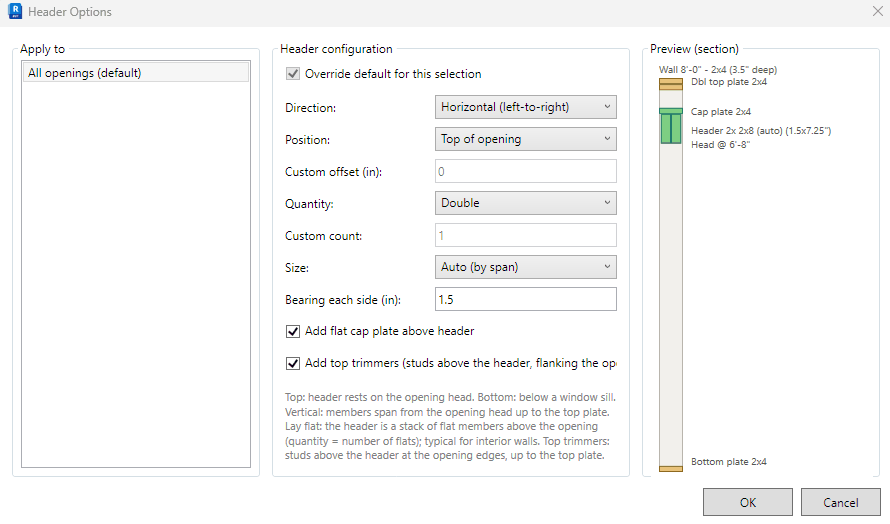
The Header Options dialog showing direction, position, quantity, size and bearing
06 — Floor Framing

Floor Framing Panel

1. Frame Floor
Generates joist framing for one or more selected floors.
  1. Select one or more floors in the model.
  2. Click Frame Floor.
  3. If a Type Preset is mapped to the floor's Revit type, framing generates immediately with no dialog.
  4. Otherwise, the Floor Settings dialog opens; configure options and click OK.
  5. If framing already exists, the plugin asks you to confirm replacement.
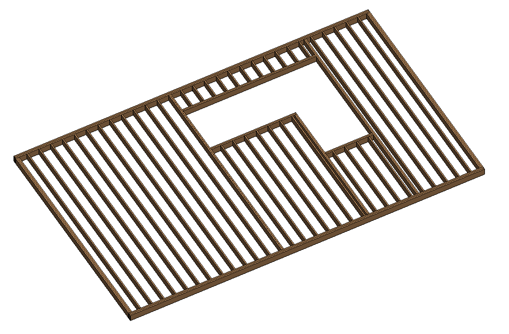
A framed floor in the Revit 3D view showing parallel joists, rim members along all edges, and headers around a floor opening
2. Framing Configuration (Floor)
Opens the Floor Settings dialog to review, edit, or save presets without requiring a floor selection.
  1. Optionally select floors in the model.
  2. Click Framing Configuration in the Floor Framing panel.
  3. Adjust settings and click Save to store as a preset, or OK to apply and close.
3. Add Floor Blocking
Inserts blocking members perpendicular to joists in already-framed floors.
  1. Select one or more framed floors.
  2. Click Add Floor Blocking.
  3. Configure blocking spacing and row count in the dialog.
  4. Click OK — blocking is placed between joists at the specified intervals.
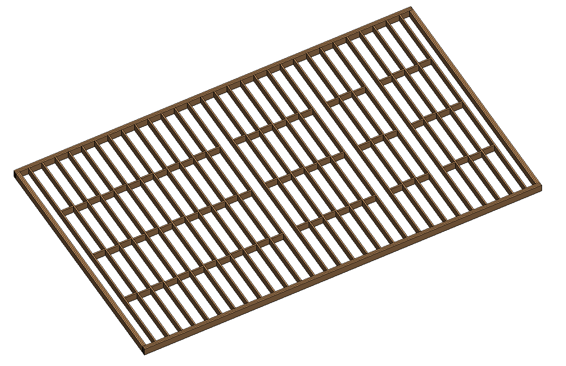
A floor framing plan or 3D view showing blocking members perpendicular to the joist span
4. Delete Floor Blocking
Removes only the blocking from selected framed floors, leaving joists, rims and openings untouched.
  1. Select one or more framed floors that have blocking.
  2. Click Delete Blocking in the Floor Framing panel.
  3. Confirm the deletion.
5. Delete Floor Framing
Removes all framing members, the assembly, and the stored state from selected floors.
  1. Select one or more framed floors.
  2. Click Delete Floor Framing.
  3. Confirm the deletion in the prompt.
Warning: This action is irreversible. All floor framing members are permanently removed.
6. Update Floor Framing
Re-runs joist framing on selected floors using their saved configuration.
  1. Modify the floor boundary or openings in Revit.
  2. Select the affected framed floors.
  3. Click Update Floor Framing.
Note: Auto-Update handles this automatically when enabled; this button forces a manual refresh.
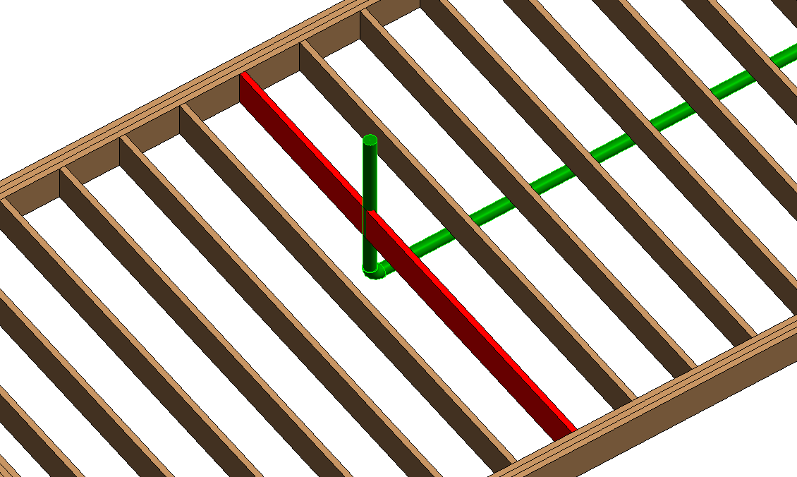
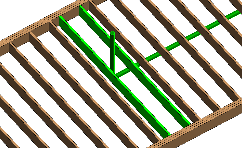
7. Shift Joists
Moves individual joist stations to accommodate mechanical or structural conflicts.
  1. Select a framed floor.
  2. Click Shift Joists.
  3. Click one or more joists in the model to identify which stations to move.
  4. In the dialog, set the offset distance and choose a mode (Keep Original / Eliminate / Eliminate + Add Special).
  5. Click OK to apply.
A floor framing 3D view or plan showing a shifted joist with a gap at the original position and the relocated joist highlighted A floor framing 3D view or plan showing a shifted joist with a gap at the original position and the relocated joist highlighted
8. Flip O.C. Layout
Cycles the joist layout origin between Start, End, and Centered along the span direction.
  1. Select one or more framed floors.
  2. Click Flip O.C. Layout.
  3. The button label updates and framing regenerates immediately with the new origin.

Floor Settings Dialog

The following fields are available in the Floor Framing Configuration dialog:
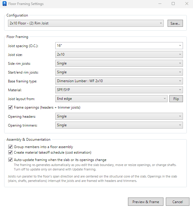
The Floor Framing Configuration dialog: joist spacing and size, rim counts, opening headers and trimmers, layout origin
Field Description
O.C. Spacing On-center joist spacing (e.g., 12", 16", 24").
Joist Size Lumber size for floor joists (e.g., 2×8, 2×10, 2×12).
Side Rim Count Number of rim members (0–4) packed inward along the span edges of the floor.
Start/End Rim Count Number of rim members (0–4) at the span start and end of the floor.
Opening Header Count Number of header members placed on each side of floor openings.
Trimmer Count Number of trimmer joists placed alongside floor openings.
Framing Type Revit family symbol used for all framing members.
Material Material applied to generated framing members.
Frame Openings When checked, headers and trimmers are generated around floor openings automatically.
Create Assembly Groups all framing into a Revit Assembly when checked.
Create Takeoff Writes member data to Comments parameters for BOM export when checked.
Auto-Update Enables automatic re-framing when floor geometry or openings change.
Layout Origin Sets the joist layout start point: Start, End, or Centered.
Saved Configs Dropdown of named presets; selecting one loads all settings immediately.
07 — Tools

Tools Panel

Export BOM

Exports a complete cut list and summary of all framed members to a Microsoft Excel workbook (.xlsx).

Scope: If one or more framed walls or floors are selected before clicking, only those elements are exported. If nothing is selected, the entire model is included.

Output workbook contains two sheets:

  • Cut List — rows grouped by element, then by member size and role, with length, quantity, and total lineal footage per group.
  • Summary — all elements aggregated by member role, size, and length, with a grand total lineal footage at the bottom.
  1. Optionally select the framed walls or floors you want to include.
  2. Click Export BOM in the Tools panel.
  3. Choose a save location and filename in the file dialog.
  4. The file is saved and opens automatically in Excel.
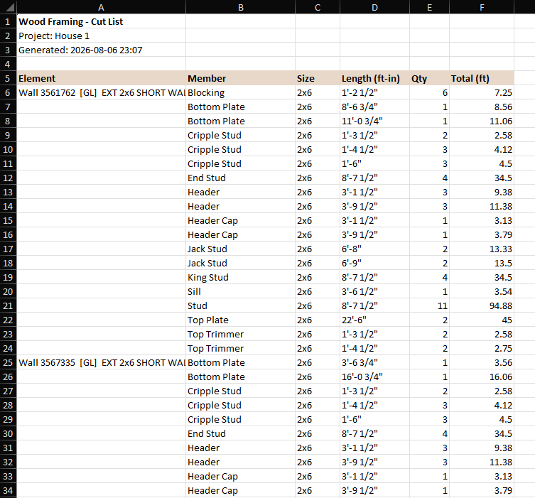
The exported Excel workbook showing the Cut List sheet and the Summary sheet tab

Type Presets

Maps Revit wall or floor types to named framing presets. Once mapped, selecting an element of that type and clicking Frame Wall or Frame Floor loads the mapped preset and skips the configuration dialog entirely.

  1. Click Type Presets in the Tools panel.
  2. In the dialog, select a wall or floor type from the list on the left.
  3. Choose a saved preset from the dropdown on the right.
  4. Click Save to store the mapping.
  5. Repeat for additional types, then close the dialog.
Tip: Preset mappings are stored per user in %AppData% and persist across Revit sessions and projects.
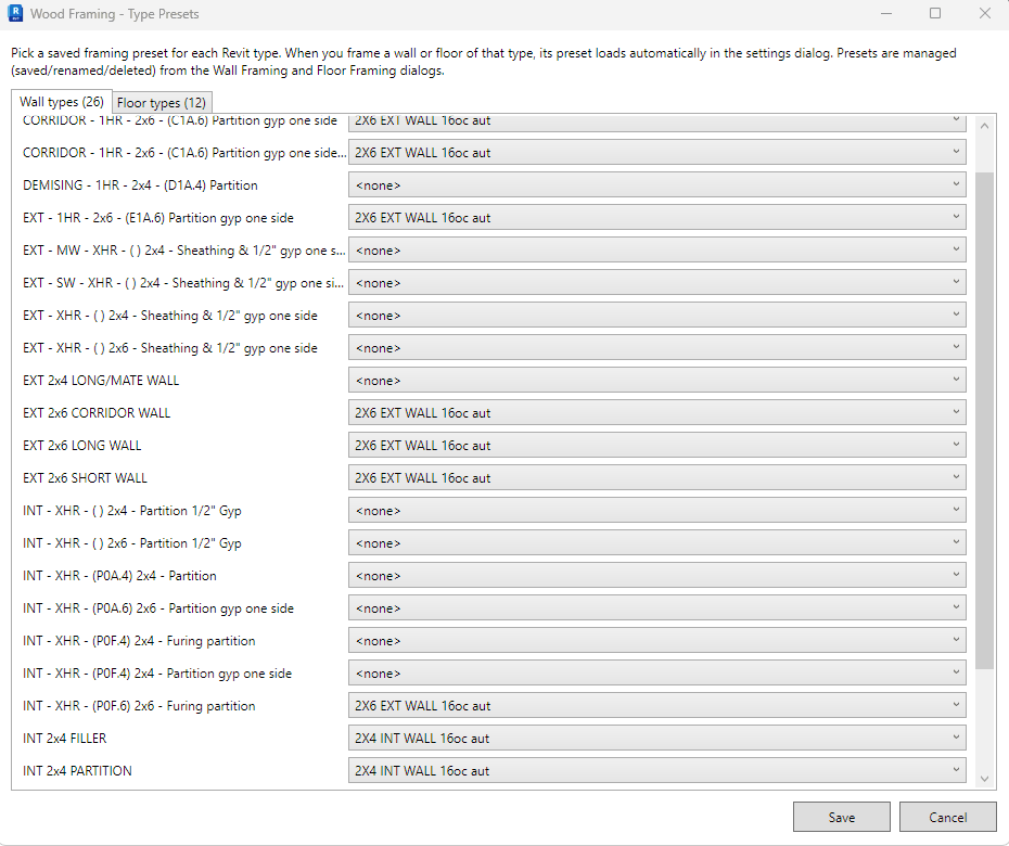
The Type Presets dialog showing Revit wall/floor types, the preset dropdown, and the Save button

Generate Assembly Views

Builds a full set of shop-drawing views for each selected framed wall or floor, straight from its framing assembly: interior and exterior elevations, both end elevations, a plan detail, two detail sections, a 3D orthographic view, a part list and a material takeoff. Each view is then dimensioned and labelled — one dimension chain per framing member type, and text-note labels whose content comes from any parameter you choose. Views land in the project browser; an assembly sheet is created only if you ask for one, so sheet composition stays under your control.

  1. Select one or more framed walls or floors. Elements that have not been framed are skipped automatically.
  2. Click Generate Assembly Views in the Tools panel.
  3. Pick a built-in preset (Detailed, Framing Only, Schematic or Views Only) or set the options by hand.
  4. Tick the views you want, choose which face the primary elevation looks at, and pick view templates and a title block if you use them.
  5. In the dimensions table, set each member type’s style, whether it measures from centres or faces, which side it sits on — or Close to element — and its offset.
  6. In the tags table, set each member type’s text style and the parameter its text comes from.
  7. Click Generate. A summary reports the views created and how many dimensions and labels were placed; expand Notes for anything that could not be done.

Built-in presets:

  • Detailed — every member type dimensioned and labelled, plus overall sizes and openings.
  • Framing Only — the structural members with their spacing and overall dimensions, lighter on component detail.
  • Schematic — overall length and height only, for quick reference.
  • Views Only (annotate later) — builds the views and leaves them clean, ready for Annotate Views.
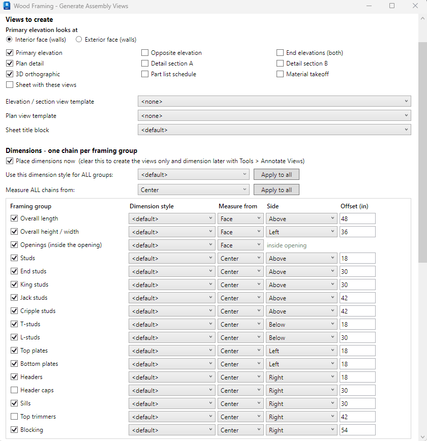
Field Description
Preset Loads a saved set of options. Built-ins — Detailed, Framing Only, Schematic and Views Only (annotate later) — plus any custom presets appear in the dropdown. Use Save…, Rename… and Delete to manage your own; built-ins are protected.
Views to create Primary elevation, opposite elevation, both end elevations, plan detail, detail sections A and B, 3D orthographic, part list schedule, material takeoff, and an optional assembly sheet holding them all.
Primary elevation looks at Interior or Exterior wall face. Orientation is decided by measuring each candidate view direction against the face you asked for, so it does not depend on how Revit happens to name the views. For floors the elevation looks across the joists.
View templates / title block Optional Revit view templates for the elevations and sections and for the plan, plus the title block family used on the sheet.
Place dimensions now / Place tags now Clear either one to create the views and annotate them later with Annotate Views.
Framing group rows One row per member type — studs, end, king, jack and cripple studs, T- and L-studs, top and bottom plates, headers, header caps, sills, top trimmers, blocking, joists, rim and trimmer joists — plus overall length, overall height and openings.
Dimension style Any linear dimension type in the project, chosen per group. The “Use this dimension style for ALL groups” row sets every group at once.
Measure from Center measures to each member centreline, so 16" o.c. framing reads 16". Face measures to the members’ faces: layout chains take the same side of every member, while an opening takes the two faces looking into it, giving the true rough opening. Openings, overall length and overall height default to Face; member groups default to Center.
Side Above, Below, Left or Right — measured from the edges of the whole assembly — or Close to element, which draws the chain at the members it measures: at the middle of their own extent, spanning only them. Ideal for cripples, jacks and sills.
Offset How far out the chain sits, in inches. With Close to element it nudges the chain off the middle of the group instead.
Minimum gap between stacked chains Chains landing on the same side stack outwards by at least this distance so they never overlap.
Extend every chain to the framing edges The chain reads edge – stud – stud – … – edge instead of stopping at the first and last member of its own group, and lets a single plate or sill still be dimensioned. Normally left on.
Tag rows One row per member type: the text style, the parameter the text is read from, whether the label rotates to run along the member, whether it carries a leader, and the side and offset of the leader band.
Text from parameter Any parameter on the member — Comments by default — plus the pseudo-parameters Type Name, Family and Type, Type Comments and Type Mark.
Annotate every created view Annotates all the graphical views just created, rather than only the primary elevation.
The Generate Assembly Views dialog: the views checklist, the dimensions table with a row per framing group showing Dimension style, Measure from, Side and Offset, and the tags table below it
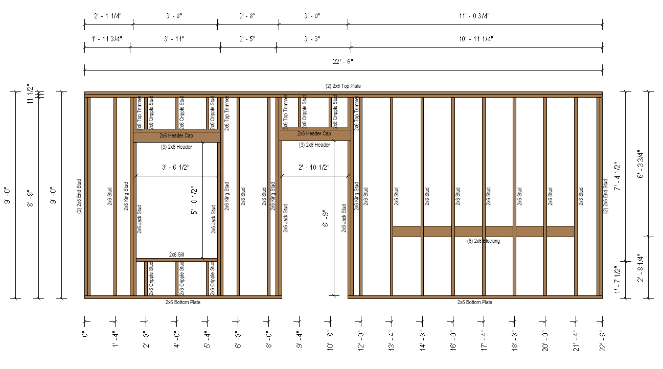
The generated assembly elevation in Revit: one dimension chain per member type, the opening dimensioned inside the opening, and rotated member labels
Tip: Custom presets are stored per user in %AppData%\WoodFraming\AssemblyViewPresets.json, so they follow you across projects just like Type Presets.

Annotate Views

Adds dimensions and labels to assembly views that already exist — the companion to Generate Assembly Views. Use it to annotate views created with the Views Only preset, to add another set of chains and tags to finished views, or to re-annotate after changing your mind about sides and offsets.

  1. Open an assembly view to annotate just that view — or run the command from anywhere else and select the framed walls and floors whose assembly views should all be annotated.
  2. Click Annotate Views in the Tools panel.
  3. Set the dimension and tag options exactly as in Generate Assembly Views, then click Annotate.
The result dialog after Annotate Views, reporting the dimensions and labels placed
Tip: The counts in the result dialog are verified after the change is committed, so they only ever report annotation that really exists in the model. Anything that could not be placed is named in the Notes section, together with the reason.

Delete Dimensions & Labels

Two commands that clean up annotation this plugin placed. Delete Dimensions removes the dimension chains and keeps every label; Delete Labels removes the text notes and keeps every dimension. Each pass records what it created on the view, so both remove the plugin’s own work and leave anything you drew by hand alone.

  1. Open an assembly view to clean just that view, or run the command from anywhere else and select the framed walls and floors to clean.
  2. Click Delete Dimensions or Delete Labels in the Tools panel.
  3. Choose Delete only what this plugin created — recommended — or Delete every one in these views, which is the fallback for views annotated by an older build where no record exists.
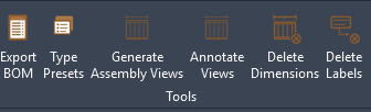
The Tools panel with the Delete Dimensions and Delete Labels buttons
Tip: Because the two are independent, you can re-dimension with different sides and offsets without losing your tags, or re-tag from a different parameter without redoing the dimensions.
08 — Troubleshooting

Tips & Troubleshooting

Framing is not updating automatically after a wall or floor change.
Open Framing Configuration for the element and confirm that Auto-Update is checked. Use Update Framing or Update Floor Framing to force a manual refresh at any time.
The wrong preset loaded when framing was generated.
Open Framing Configuration to see which preset is currently active for that element, and switch to the correct one from the saved configs dropdown before re-framing.
Members are missing after copying a framed wall or floor.
The plugin detects copied elements and resets their inherited framing state to prevent data corruption. Re-run Frame Wall or Frame Floor on the copied element to generate fresh framing.
The BOM export shows no data or empty rows.
Confirm that the walls or floors have been framed and that Create Takeoff was enabled in their settings. Only framed elements with member data written to Comments parameters appear in the export.
A Type Preset is not applying when Frame Wall or Frame Floor is clicked.
All selected elements must share the same Revit type for the preset mapping to trigger. If the selection contains mixed types, the configuration dialog opens instead. Select only elements of the mapped type.
Studs overlap or leave a gap where two walls meet at an L-corner.
Corner resolution was reworked in v2.9 to decide consistently which wall runs through the corner. If a corner still looks wrong after editing wall geometry, re-run Update Framing on both walls so each rebuilds against the latest join. The run notes log how each corner was resolved.
Generate Assembly Views produced fewer views than elements selected.
Only framed walls and floors generate views; unframed elements in the selection are skipped. Confirm each one has been framed first, then re-run the tool. The summary dialog reports the exact number of views created.
The dialog reported dimensions and labels, but nothing appears in the view.
A view template is locking the crop region, so correctly placed annotation cannot be shown — the Notes section of the result dialog says so. Turn Crop View off in that view, or clear the template. From v2.10.1 the reported counts are verified after the change is committed, so they only ever count annotation that really exists.
An opening dimension reads about one stud thickness too wide.
That row is measuring from Center. Set Measure from to Face for the Openings group: the chain then runs between the two faces that look into the opening, which is the real rough opening. Presets saved before v2.10.3 need this set once and re-saved.
One dimension chain is missing while the rest are fine.
Expand Notes in the result dialog — it names the chain and the reason. Each chain is created in its own transaction, so one Revit rejects no longer takes the others with it. Switching that row to Measure from Face usually resolves it, since every family has faces.
Two labels are printed on top of each other.
Members that read the same text, run the same way and touch each other are merged into a single label prefixed with the count, such as “(2) 2x4 Top Plate”. If two still overlap, the members carry different Comments text — check their Comments parameter.
Dimension chains from different member types overlap.
Increase Minimum gap between stacked chains, move one group to a different side, or set the crowded group’s Side to Close to element so it sits beside its own members instead of out beyond the assembly.
Revit says the add-in failed to load.
The DLL was blocked by Windows: right-click WoodFraming.dll, open Properties and click Unblock. Also confirm the DLL matches your Revit version.
The plugin was updated but the old behaviour remains.
The DLL cannot be replaced while Revit is open. Close Revit, run the update script, then reopen Revit.
"No structural framing families are loaded."
Load one from Insert > Load Autodesk Family > Structural Framing > Wood > Dimension Lumber.
The assembly is named after the wall type instead of the wall mark.
The wall's Mark parameter is empty. Fill it in and re-frame, or rename the assembly type manually.
The elevation view has no dimensions.
Check that the group is ticked in the dimensions table, and that “Extend every chain to the framing edges” is on — without it a group needs at least two members before it can be dimensioned. If the family exposes no centre reference planes, set Measure from to Face for that row.
A header is missing on a door near a wall end.
The header is clamped to the wall length, and jack or king studs that would fall outside the wall are skipped. A warning lists the affected wall.
A header is pushed down or overlaps the top plate.
The opening head sits too close to the wall top, so the header is lowered to fit below the top plate and a warning is shown. Choose a smaller header size in Header Options.
The "Bottom" header position was ignored on a door.
Bottom position applies only to windows, since doors have no sill. The plugin falls back to Top and warns.
Plates or sills are not laid flat.
The framing family must support cross-section rotation. Generic structural framing families do; some custom families do not.
Studs have the wrong cross-section size.
The chosen base family has no b/h (or Width/Depth) type parameters, so sizes cannot be set. Use a dimension-lumber family — a warning is shown when this happens.
A curved wall was skipped.
Only straight, line-based walls are supported. The completion dialog lists every skipped wall.
Members were placed but are invisible.
Check the view range — studs sit inside the wall height — and confirm Structural Framing is visible in Visibility/Graphics (VG).
The wrong wall height was framed.
The plugin uses the wall's Unconnected Height or top constraint. Attached or profile-edited walls may differ; verify in an elevation.
Limitations: Straight walls only, no arcs. Single stud rows, no staggered studs. Sloped walls are framed square-cut at the top. Header sizing follows a span rule-of-thumb and is not engineered — always review with your structural engineer. Vertical, lay-flat and multi-ply headers are geometric placements, not structural designs.
FlowFraming v2.10.3 — Revit Plugin Documentation