Introduction
CFS Framing is a Revit plugin that frames walls and floors in cold-formed steel (light gauge steel). It places base and top track, studs at your O.C. spacing, jambs, headers, sills, cripple and infill studs at every opening, the studs at L corners and T intersections, bridging, floor joists with rim track, and clip connectors — all as normal Revit structural framing grouped into an assembly per wall or floor.
When the framing is done it exports a cut list and weight takeoff to Excel and builds dimensioned shop drawings from the same assemblies. It follows the same workflow as Wood Framing: settings dialogs, reusable presets mapped to your wall and floor types, auto-update and shop-drawing presets.
Getting Started
System Requirements
- Autodesk® Revit® 2024, 2025 or 2026
- Windows 10 or Windows 11 (64-bit)
- Microsoft Excel or any spreadsheet app to open the exported BOM (optional)
- A free FlowFraming account (create one here) — the same account works for Wood Framing
- Internet connection to sign in and activate — after that CFS Framing keeps working offline for up to 7 days
Installation
- Sign in at flowframingtool.com/account, choose CFS Framing and click Download installer.
- Close Revit and run
CFSFraming-Setup-x.y.z.exe. It installs the add-in into every supported Revit version on the computer — no administrator rights needed. - Open Revit. A new CFS Framing tab appears in the ribbon.
- Click Tools > License, sign in with your account and start the free trial (or activate your licence).

Loading the Families
The installer includes the CFS families. The first time you run Frame Wall or Frame Floor in a project, CFS Stud.rfa and CFS Tracker.rfa are loaded automatically. Copies are also in Documents\CFS Framing\Families if you prefer to load them yourself:
- Insert > Load Family and pick
CFS Stud.rfaandCFS Tracker.rfa. - For clip connectors, also load
CFS Stud_Clip.rfa.
You never need to create types: the plugin creates the galvanized-steel material and one family type per section it uses (CFS 362S162-43, CFS 362T125-43… in imperial, 90CA085, 92C085… in metric) the first time it needs them. The grid-marker detail family used in shop drawings is loaded automatically.
License & Activation
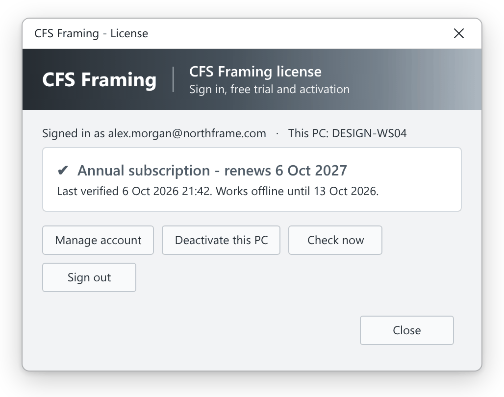
Click License in the Tools panel to sign in, start your free trial, check your licence or move it to another computer. CFS Framing has its own licence and trial, separate from Wood Framing, but uses the same FlowFraming account.
- The trial runs 14 days on the computer where you start it.
- Each licence works on up to two computers. Deactivate one from the License window or from your account page to move it.
- After activating, CFS Framing works offline for up to 7 days and quietly re-checks whenever you are online.
Updating & Uninstalling
- To update, download the latest installer from your account page, close Revit and run it. Settings and presets are kept.
- To uninstall, use Windows Settings > Apps > Installed apps > CFS Framing for Revit. Your presets and sign-in stay in
%AppData%in case you reinstall.
Concepts
Every framed wall or floor gets a Revit assembly holding all its members. Assemblies are what the shop drawings, the BOM and Update Framing work from.
A preset is a named set of framing settings — sections, spacing, openings, intersections, comments. Map a preset to a wall or floor type with Type Presets and framing that type skips the dialog.
Each wall and floor remembers what the plugin placed and with which settings. With auto-update ticked, changing the wall or one of its openings re-frames it inside the same assembly, so its views survive.
Every member's Comments read like 362S162-43 Special Jamb Left. The pattern per role is editable in the settings dialogs; the plugin itself reads a hidden tag, so changing the text never breaks Shift, Bridging or the BOM.
Units: SSMA & METALCON
CFS Framing follows the project's length units (Manage > Project Units > Length), checked at the start of every command. Only sizes and names change — the framing rules are the same.
| Imperial project | Metric project | |
|---|---|---|
| Catalog | SSMA | METALCON (Cintac, Manual de Diseño) |
| Studs / joists | 362S162-43 … | 40CA085 … 250CA16, perforated 90CA085p |
| Track | 362T125-43 … | 42C085 … 253C10 |
| Defaults | 362S162-43 @ 16" O.C. | 90CA085 @ 400 mm, track 92C085, joists 200CA16, rim 203C10 |
| BOM | ft, lb/ft, lb | m, kg/m, kg |
Wall Framing Panel
Select one or more straight walls and click Frame Wall. If the wall type is mapped to a preset, the walls are framed straight away; otherwise the settings dialog opens first. Framing Settings always opens the dialog — with nothing selected it is a place to review and save presets.
Framing Settings
The dialog picks the stud and track sections, the O.C. spacing and layout start, end-stud counts, the head-of-wall condition, the opening families and the L-corner / T-intersection build-ups. Preview & Frame shows the member count before anything is placed. A second tab sets the Comments text per member role.
Openings
Doors, windows and wall openings are framed to the real rough opening (Rough Width / Rough Height, then the measured geometry, then the nominal size). Pick the build-up per opening, per family type or as a default:
| Headers | Back-to-back · boxed · single with strongback · single track |
| Jambs | Single · boxed · back-to-back |
| Also placed | Sill (windows), cripples above the header and below the sill, infill studs |
The options dialog draws the header section and jamb plan from the sections you selected. An opening closer to the wall end than one stud width is treated as open on that side: one jamb only, and the header runs to the end of the framed range.
Corners & Intersections
L corners and T intersections are resolved once per corner, so the two walls never both decide they run through. Choose the connection build-up in the settings, or None to place only the normal end and O.C. studs. The dialog draws each connection as it will be built.
Sloped & Gable Tops
The top of the wall is read from its real geometry — edited profile, top attached to a roof or plain height. The top track is cut into one piece per slope (a gable is two tracks meeting at the ridge) and each stud stops square under the track. Studs too short to place at a low end are left out instead of skipping the wall.
Bridging
Add Bridging places rows across the studs of framed walls. Choose the profile (track, stud or channel, any size), the orientation, the layout — one full-length piece per row or one piece per bay — and the height, number of rows and spacing. Rows never cross an opening; rows above headers and below sills still run through the cripples. Delete Bridging removes them.
Shift Studs & Multiple Studs
Shift Studs moves a common stud along the wall, with a before / after plan preview. Multiple Studs sets the total number of studs at a stud line or wall end (1–8): nested, back to back or toe to toe, added toward the start, the end or centred. Both are stored on the wall, so Update Framing and auto-update keep them.
Update, Flip & Delete
- Update Framing re-frames the selected walls from the settings they were framed with, keeping shifts, multiple studs and bridging.
- Flip O.C. Layout cycles the layout start of the selected walls (or, with nothing selected, the default for new framing).
- Delete Framing removes exactly what the plugin placed — hand-placed members are left alone.
Floor Framing Panel
Select floors and click Frame Floor. Joists are laid out along the span direction at your O.C. spacing, rim track runs around the edges, and openings get headers and trimmers. Add Blocking places rows perpendicular to the joists; Shift Joists, Flip O.C. Layout, Update Framing and Delete Framing work as on walls.
Connectors Panel
Clip angles are placed from the face-based CFS Stud_Clip family, hosted on the member they are fastened to so they travel with the framing.
| Place wall connectors | Stud to track (seat on the track web, leg on the stud web) and stud to header |
| Place floor connectors | Joist to rim track, only on joist ends that reach a rim |
| Delete connectors | Removes only the plugin's clips |
Sizes follow the RCA range (CFS RCA225-68…) or "as drawn" for your shop's own clip. Clips are added to the wall's assembly, so they appear in shop drawings, and they are counted in Export BOM.
Tools Panel
Export BOM
Writes an Excel workbook (no Excel needed to create it) with three sheets:
- Cut List — every piece grouped per wall and floor, each closed with its own subtotal.
- Summary — totals by member role.
- Grand Total — one row per section designation: pieces, lineal length, developed width, weight per length and weight, plus clip connectors and a weight-by-element table.
Framing inside linked models is included when you tick the option; each link instance counts separately. Weights are bare steel from the developed width, about 2% under published values.
Type Presets
Maps each wall and floor type to a framing preset and, in the second column, a shop-drawing preset. Framing or drawing a mapped type then uses its preset without asking.
Shop Drawings Panel
Shop Drawings builds (or reuses) each selected element's assembly and creates the assembly views — elevations at the face you choose, plan detail, sections, 3D, part list, material takeoff and an optional sheet — then dimensions and labels them. Dimensions are one chain per framing group (studs, jambs, headers, track, bridging, joists…), each with its own style, side, offset and centre-or-face anchor. Labels are text notes read from any parameter, merged into one "(2) …" note where members are packed together.
Presets & View Names
- The preset bar has New, Save, Save as, Rename and Delete. Shop Drawing Presets opens the same settings without generating anything.
- Every view and the sheet have a name pattern:
{assembly}{face}{n}{type}{mark}{level}. - The General tab can add the host wall, its doors and windows and other hosted elements to the assembly before the views are made.
- Where a model grid crosses the wall, a grid marker is drawn in the elevations. Sloped and gable tops get height and peak-position dimensions.
Annotate Views & Update Dims / Tags
Annotate Views dimensions and labels existing assembly views with a preset. Update Dims / Tags re-runs the recipe each view was created with — use it after re-framing.
Delete Dimensions & Labels
Each pass records its own elements on the view, so these remove exactly the plugin's dimensions or labels and nothing you drew by hand.
Tips & Troubleshooting
CFS Stud.rfa and CFS Tracker.rfa from Documents\CFS Framing\Families (see Loading the Families).